HVAC (Heating, Ventilation, Air Conditioning)
Sunday, June 25, 2006

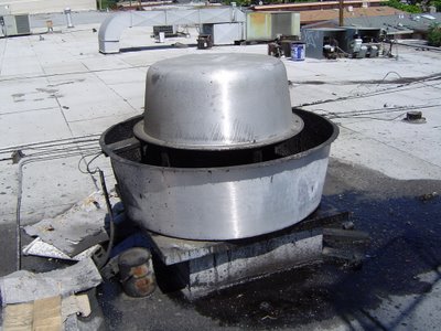
This picture is from a facility that was abandoned a while back. You see grease here on the roof either because the Kitchen hood did not have any grease filters, or the personnel just removed the filters and operated the hood without them. People don't like grease filters because they sometimes catch fire. But they catch fire because you don't periodically wash them and one day when the heat is really high the grease collected on the filters starts burning.
Sometimes grease receptacles are provided at the fan, on the roof. But I am not a big 'fan' of that scheme. Out of sight, out of mind grease receptacle is seldom attended to.
A good kitchen exhaust system consists of grease hood with filters, grease receptacle, and fire suppression system; all this with an upblast fan on the roof. But you still need to periodically empty the grease receptacle, wash the filters, and check the fan on the roof.
Saturday, June 24, 2006
 Kitchen Grease Filters and grease receptacle
Commercial kitchens are normally equipped with large hoods housing grease filters. The air exhausted through the hood is made to abruptly change its direction making the accompanying grease deposit on the "filter." The filter assembly is slightly sloped so that grease drains down into a receptacle. See the handles on the grease filters in the picture? The filters should periodically be taken out and washed. Kitchen hoods exhaust large amounts of air. Provision should be made to provide make-up air in the area. Often "compensating" hoods are used that provide make-up air around the periphery of the hood.
Wednesday, June 21, 2006

People normally don't forget to bring outside air (fresh air) to an air handling unit (AHU), but generally Fan Coil Units are not treated the same way. May be because Fan Coil Units circulate smaller amounts of air and designers don't see it necessary to bring the very small amount of required fresh air. But when fan coil units are the only source of conditioned air in a habitable space, bringing fresh air to the FCU is imperative. Ducted return is preferable but in this case the FCU had bottom return and the designer supplied fresh air close to the unit.
Once again in this hotel room scenario the fresh air duct runs in a shaft accessible from the corridor.

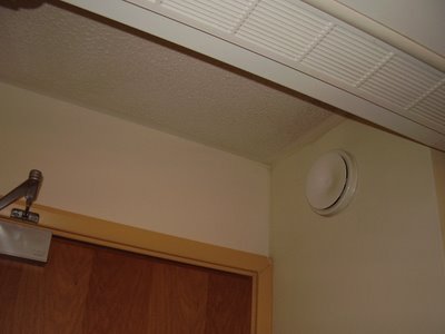
I found this toilet exhaust in a hotel room. For bigger bathrooms it is a good idea to have a separate exhaust over shower/tub too; this way you would avoid moisture spreading in the bathroom and fogging the mirror.
In the case above it was a small toilet and just one air intake served the whole area. See how the exhaust goes to a shaft accessible from the corridor (on the other side). Toilet exhaust is generally designed for 10 air changes per hour (or one air change in every six minutes). To compute the required air flow, calculate the volume of the toilet (lengthXwidthXheight) in cubic foot and then divide that number by 6 minutes, this would give you the required air volume flow rate in cfm (cubic foot per minute). Make up air (the same amount that you are exhausting) must be provided to ensure that you won't create a negative pressure in the toilet and make it difficult to open/close the toilet door. For smaller toilet exhaust cfm's, make up air can come through the undercut of the door (the distance between the bottom of the door and the finished floor). For larger amounts of air you need to have a transfer grill that would bring the required make up air from the adjacent room. For really big toilets you should think of providing some conditioned air. For example if you need an exhaust of 500 cfm, you may think of providing 300 cfm of conditioned air and transfer the rest from the adjacent room, using transfer grill.


